Next: Ping-Pong Delay Up: Delay-Based Filters & Effects Previous: Feedforward Comb Filters
The difference equation for this filter is given by:
![$\displaystyle y[n] = b_{0}x[n] - a_{M}y[n-M].
$](img30.png)
 .
.
 ,
,  , and
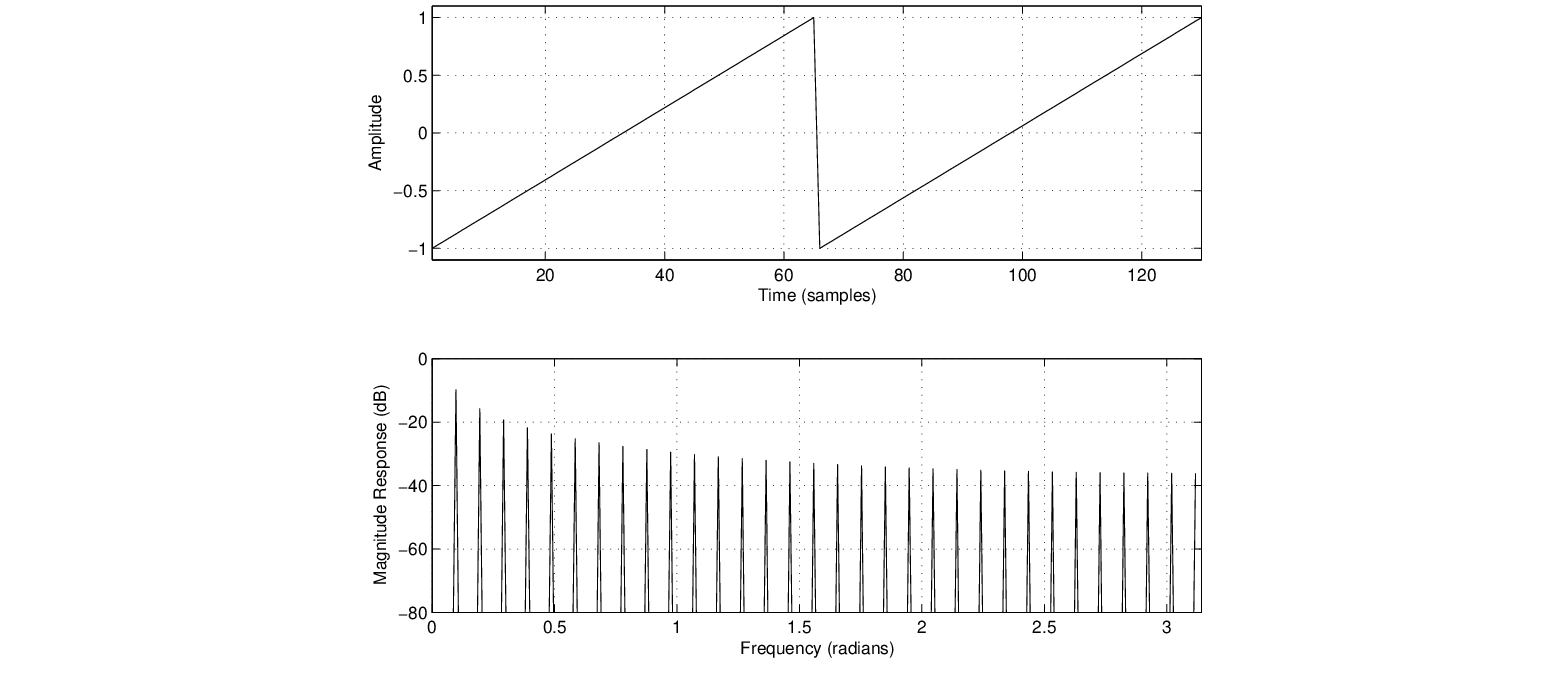
, and  = 0.6 is shown in Fig. 10.
, , and = -0.1, -0.5, and -0.9.

| ©2004-2025 McGill University. All Rights Reserved. Maintained by Gary P. Scavone. |
![\begin{figure}\begin{center}
\begin{picture}(3.9,0.9)
\put(0.27,0){\epsfig{fil...
...0.78){$b_{0}$}
\put (3.9,0.65){$y[n]$}
\end{picture} \end{center}
\end{figure}](img29.png)